
E6/E6T/L300Motorcycle Display User Manual
Find complete E6/E6T/L300 instructions, from installation and wiring to everyday use.
Reading guide and scope
This manual explains installation, connection, settings, everyday use and basic troubleshooting.
00.01Safety message definitions
00.02Recommended reading order
Installers: read the safety instructions, power wiring, display installation and post-installation checks first.
First-time users: after installation, read the home screen, phone connection and Bluetooth helmet/headset chapters.
Regular users: consult settings, OTA updates, tire pressure and troubleshooting as needed.
00.03Scope
This manual applies to the E6/E6T/L300 motorcycle display. Tire pressure monitoring requires optional sensors. Package contents depend on the purchased kit. Screens may differ by software version; refer to your actual device.
Safety instructions
Follow these requirements to prevent accidents, fire, electric shock, equipment damage or vehicle faults.
01.01General safety requirements
Use the product only after correct installation and successful functional checks. Incorrect installation may cause accidents or equipment failure.
Follow the installation and operating steps in this manual.
Do not disassemble, repair or modify the display, power cable or accessories yourself.
Before every ride, check that the display, mount, power cable and optional sensors are secure and undamaged.
Stop using the device and disconnect power immediately if you notice damage, unusual odors, smoke, excessive heat, abnormal sounds or vibration.
Keep foreign objects out of the display ports and openings.
Keep the product and detachable small parts out of children's reach.
01.02Riding safety
Do not operate the device, enter information or change settings while riding. Park the vehicle safely before operating the device.
Install the display where it does not obstruct your view, instruments, mirrors or vehicle controls.
Do not let cables or other parts interfere with steering, throttle, brakes, clutch or suspension movement.
Maps, navigation and tire pressure readings are aids only. The rider remains responsible for watching the road, obeying traffic rules and riding safely.
01.03Electrical safety
Switch off the engine and disconnect the vehicle battery before installation. Working on live wiring may cause short circuits, sparks, fire, electric shock or injury.
Wire the device for these supply conditions: B+ to +12 V; ACC must measure 0 V with ignition off and 11–14.4 V with ignition on.
Use a multimeter to confirm the ACC signal and polarity before connection. Do not identify vehicle wiring by color alone.
Connect GND securely to the battery negative terminal or a reliable vehicle ground point.
Stop using and replace any power cable that is damaged, pinched, exposed or has a loose connector.
Keep cables away from hot engine and exhaust parts, sharp edges and moving components.
01.04Environmental and installation precautions
The display is rated IP67. With ports and seals correctly closed, the product undamaged and correctly installed, it resists dust and temporary immersion under the standard's specified conditions. IP67 does not cover pressure washing, steam cleaning or prolonged immersion. This rating applies only to the display, not to tire pressure sensors, mounts, wiring or other accessories.
Operating temperature: -20 °C to 70 °C. Stop using the device outside this range and allow it to return to an acceptable temperature before switching it on.
Do not use the device in corrosive gases, flammable or explosive environments, persistent salt spray, strong chemical splashes or conditions involving prolonged immersion.
Make sure all screws, ball joints and mounts are tight. Loose parts may fall off while riding.
After installation, turn the handlebars fully left and right. Check that cables are not stretched or pinched and do not affect control.
Heavy rain may affect wireless signal stability.
01.05Children and small-part safety
Keep the product and detachable small parts out of children's reach. The following coin-cell battery precautions apply only to kits with tire pressure sensors.
For sensor battery replacement, see Chapter 09; for sorting batteries and packaging for disposal, see Chapter 12 。
Product, package contents and specifications
Check the contents after unpacking. Some kits do not include optional tire pressure sensors.
02.01Package contents
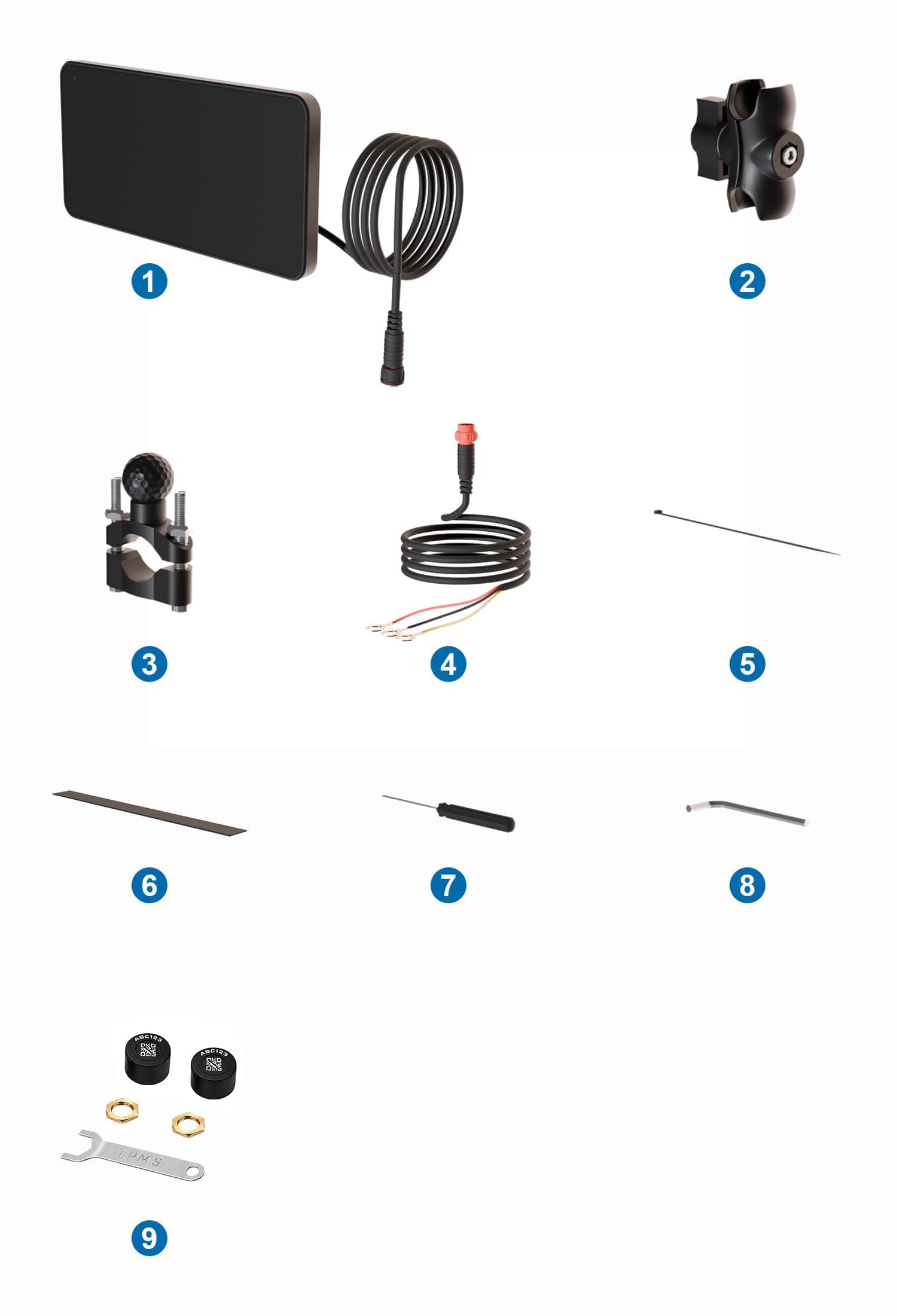
| No. | Item | Quantity | Notes |
|---|---|---|---|
| 1 | Display unit | 1 | Rear ball mount preinstalled; aftermarket accessory |
| 2 | Double-socket mounting arm | 1 | Connects the display's rear ball mount to the handlebar ball mount and allows angle adjustment |
| 3 | Handlebar ball mount | 1 | Clamps onto the handlebar and connects to the mounting arm through its ball joint |
| 4 | Power cable | 1 | Includes ACC, GND and B+ |
| 5 | Cable ties | 1 | For securing cables |
| 6 | Anti-slip pad | 1 | Wraps once around the handlebar, between the handlebar and clamp, to prevent slipping |
| 7 | Mini screwdriver | 1 | Included assembly tool |
| 8 | Hex socket wrench | 1 | Included assembly tool |
| 9 | Tire pressure sensor kit | Optional | 2 sensors per kit, each with 1 CR1632 battery installed; includes the matching wrench and nuts |
02.03Technical specifications
| Item | Specification |
|---|---|
| Display protection rating | IP67 |
| Operating input voltage | DC 5–14 V |
| ACC detection conditions | Ignition off: 0 V; ignition on: 11–14.4 V |
| Operating temperature | -20 ℃~70 ℃ |
| Storage temperature | -30 ℃~80 ℃ |
02.04Optional tire pressure sensor specifications
| Item | Specification |
|---|---|
| Battery | CR1632 (installed in sensor) |
| Measurement range | 0–116 psi(0–8 bar) |
| Measurement accuracy | Approximately ±1.5 psi (±0.1 bar) |
| Alarm thresholds | User-adjustable on the device |
02.05General environmental limits
Switch the device off and keep it dry before storage. Avoid prolonged direct sunlight.
Do not use or store it in corrosive gases, flammable or explosive environments, persistent salt spray or strong chemical splashes.
Do not direct pressure washers or steam cleaners at the display, ports, cables or sensors.
If condensation forms after moving the device from a cold place into a warm, humid place, let it dry completely before applying power.
Installation
Choose a position that is easy to see without obstructing your view or vehicle controls.
03.01Installation steps
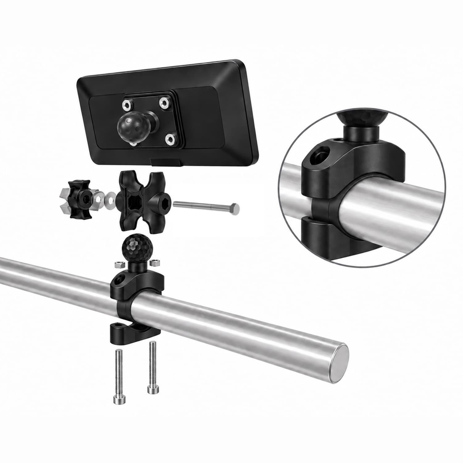
-
Secure the handlebar ball mount
Wrap the long anti-slip pad once around the handlebar at the installation point, keeping it flat. Place the upper and lower clamp halves around the pad and secure them with the supplied screws. The pad must sit between the handlebar and clamp.
-
Fit the double-socket arm
Loosen the arm's adjustment knob and fit one socket over the handlebar mount's ball. Do not fully tighten it yet.
-
Attach the display
Support the display and insert its preinstalled rear ball into the other socket. Check that both balls are seated correctly. Lightly tighten the knob to hold the display, then adjust the angle. No separate rear ball installation is needed.
-
Adjust the angle
Sit in your normal riding position and adjust the screen for easy viewing with minimal reflections.
-
Tighten the clamp and arm
Hold the display in position while tightening the handlebar clamp fasteners and arm adjustment knob. Check that the display and all joints are secure.
03.02Post-installation checks
The display and mount are secure, and the screen does not change angle by itself.
The screen does not obstruct the road, instruments, mirrors or vehicle controls.
The mount and cables do not interfere with control when the handlebars are turned fully left or right.
Cables are secured without stretching, pinching, rubbing or contact with hot parts.
The device responds correctly when the ignition is switched on and off.
Power wiring
Installation by someone experienced with vehicle electrical systems is recommended. Disconnect the battery before wiring.
04.01Wire functions
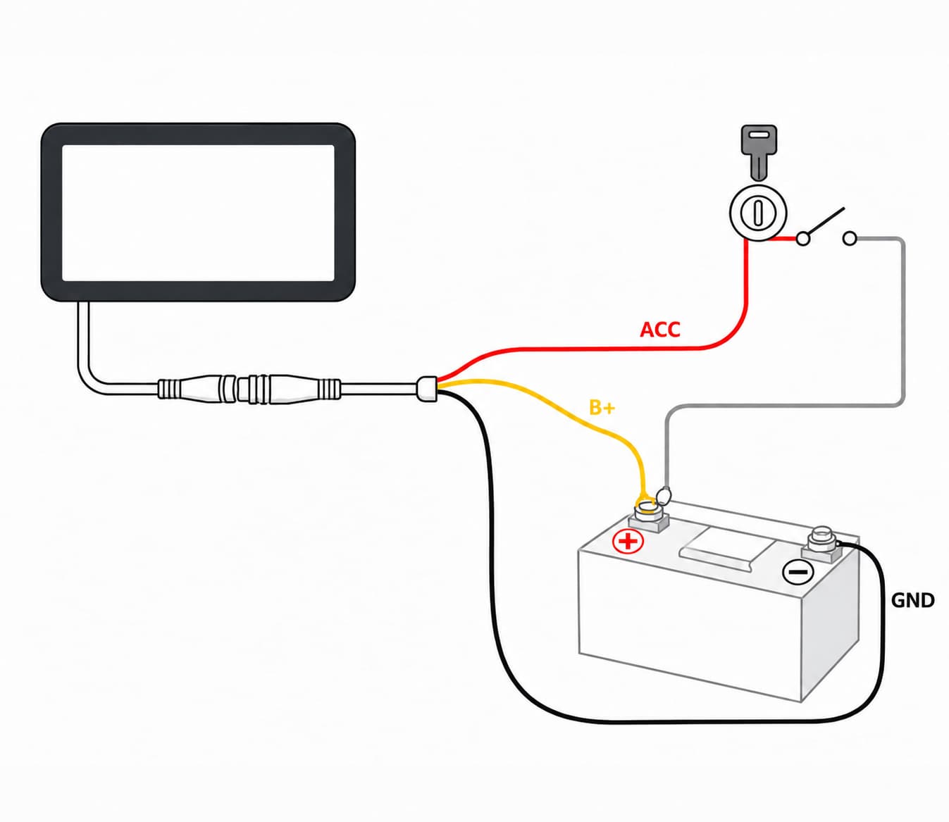
Red (ACC): connect to the vehicle's ACC supply. Confirm with a multimeter: 0 V with ignition off and 11–14.4 V with ignition on.
Black (GND): connect securely to the battery negative terminal or a reliable vehicle ground point.
Yellow (B+): connect to the battery positive terminal (+12 V) for a stable supply.
04.02Wiring steps
-
Switch off vehicle power
Switch off the engine, remove the key and disconnect the battery.
-
Identify vehicle wiring
Use the vehicle service documentation and a multimeter to identify ACC, battery positive and ground.
-
Make the connections
Connect the three wires as described above. Check polarity, secure every connection and insulate properly.
-
Secure the cables
Use cable ties, keeping cables away from hot parts, sharp edges and moving components. Leave enough slack for steering.
-
Restore power and test
Reconnect the battery and check that the display starts and shuts down normally with the ignition.
04.03Voltage measurement and power checks
Identifying ACC requires comparing voltage with ignition off and on. This diagnostic work should be performed by someone experienced in vehicle electrics, using the vehicle service documentation. Disconnect power before making, insulating or securing connections. Do not use resistance or continuity mode on live wiring, and do not bridge terminals with test probes.
After wiring, keep the vehicle stationary and verify startup with ignition on and shutdown with ignition off. Check the connectors, cables and vehicle electrical system. Stop testing immediately if anything is abnormal and follow Chapter 13.
Getting started and home screen
05.01Initial startup and setup order
First complete the Chapter 03 installation checks and Chapter 04 power tests. Once the display starts with the ignition, park safely and complete the following settings.
Open settings, select the system language, and check the date, time and display format.
Adjust the backlight and select Light, Dark or Auto theme for clear viewing while parked.
Check the Bluetooth device name. For the first phone connection, follow Chapter 06 or Chapter 07.
For audio, follow Chapter 08 to connect a helmet or headset to your phone.
If optional sensors are installed, enable tire pressure monitoring and follow Chapter 09 for pairing and checks.
Record the model, serial number and software version under Settings > System > About for future support.
05.02Home screen items
Under “Settings > General > Tire Pressure Information”, select “On” or “Off”. When off, the lower-right area shows a motorcycle image. When on, it also shows front and rear tire pressure and temperature. Tap the motorcycle area to open the tire pressure page after enabling this option.
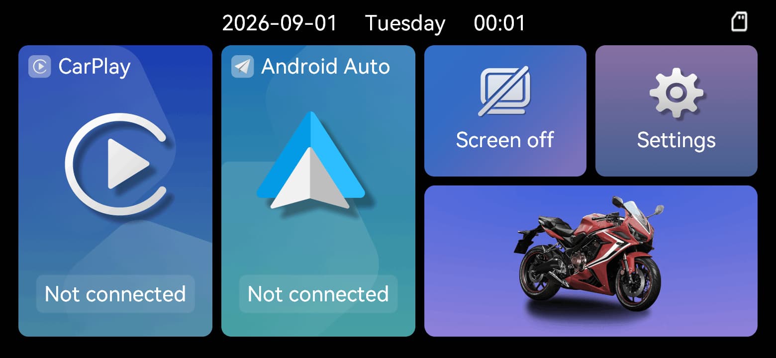
Tire pressure information off
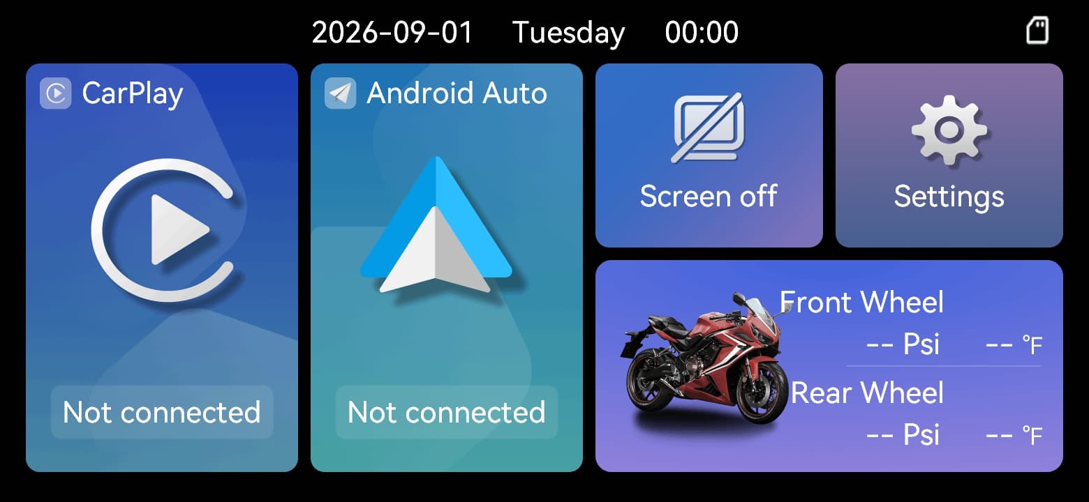
Tire pressure information on
| No. | Function |
|---|---|
| 1 | Date, day and time |
| 2 | Apple CarPlay |
| 3 | Android Auto |
| 4 | Screen Off |
| 5 | Settings |
| 6 | Tire pressure monitoring (optional; tap the motorcycle area at the bottom right) |
05.03Turning the screen off and waking it
Tap Screen off on the home screen to turn off the display. If the device has power but the screen is blank, tap it to wake it and check the brightness. For tire pressure pairing and settings, see Chapter 09; for vehicle power checks, see Chapter 04.
Apple CarPlay
Enable both Bluetooth and Wi-Fi on your iPhone before the first connection.
06.01First connection
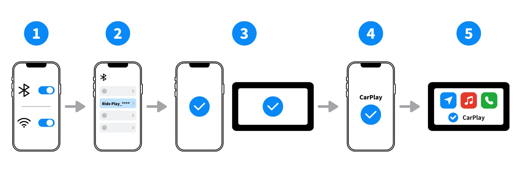
Select the Bluetooth name shown on your display when pairing
-
Enable wireless features
Turn on Bluetooth and Wi-Fi on the iPhone.
-
Select the display
Select Ride Play_**** in the Bluetooth device list. The four characters represented by asterisks vary by device.
-
Confirm Bluetooth pairing
Accept the pairing requests on the iPhone and display when prompted.
-
Allow CarPlay
When asked to use CarPlay, select Use CarPlay.
-
Wait for connection
The display will switch to CarPlay after a short wait.
06.02Compatibility requirements
Use an iPhone that supports CarPlay and wireless CarPlay. Compatibility depends on the iPhone model, iOS version and region.
Update the iPhone to an Apple-recommended compatible iOS version and make sure Siri and CarPlay are not restricted.
Both Bluetooth and Wi-Fi must be on. Phone hotspots, VPNs, enterprise device management or other wireless connections may interfere.
06.03Later connections
The system will try to reconnect when Bluetooth and Wi-Fi are on, the devices are in range and the pairing record is saved.
06.04If connection fails
Move the iPhone near the display and confirm Bluetooth and Wi-Fi are on.
Confirm the selected name is Ride Play_**** and the phone is not connected to another device with the same name.
Turn the phone's Bluetooth and Wi-Fi off and on, then open CarPlay again.
If the problem remains, restart both the phone and display.
Finally, delete old pairing records on both devices and repeat the first-connection steps.
Android Auto
Supports smartphones running Android 11.0 or later.
07.01First connection
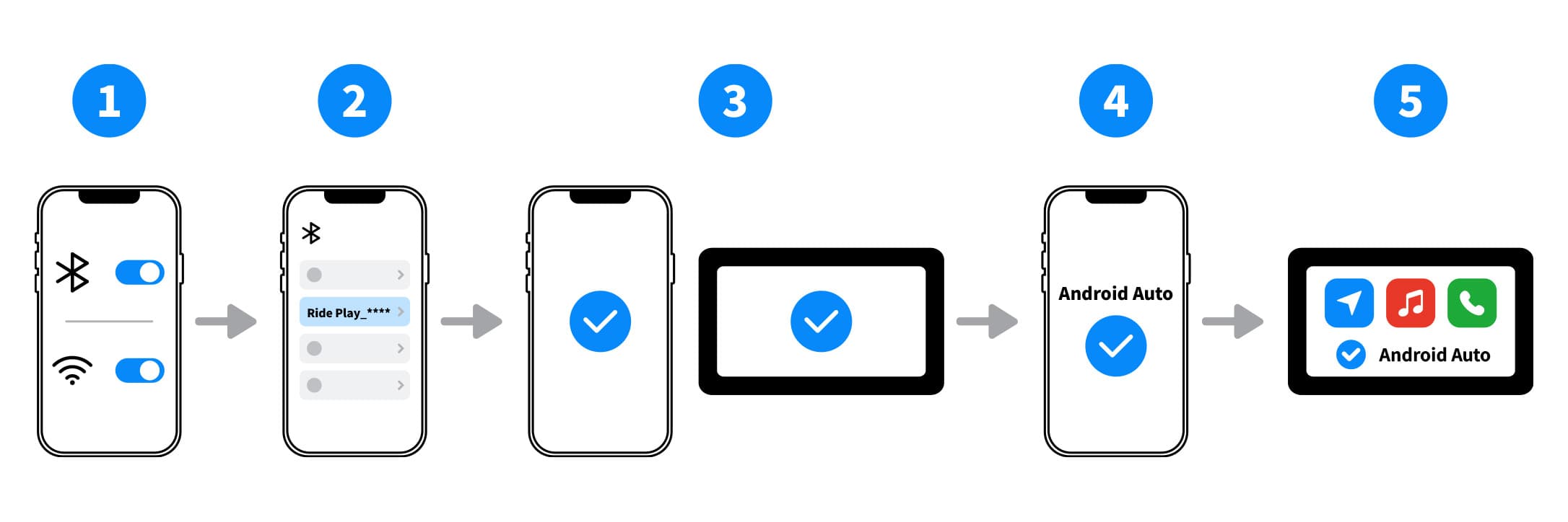
Select the Bluetooth name shown on your display when pairing
-
Check the system version
Confirm the phone runs Android 11.0 or later.
-
Enable wireless features
Turn on Bluetooth and Wi-Fi on the phone.
-
Select the display
Select Ride Play_**** in the Bluetooth device list. The four characters represented by asterisks vary by device.
-
Confirm pairing
Accept the pairing requests on the phone and display when prompted.
-
Complete permissions
Follow the phone's prompts to complete the permissions and settings required for Android Auto.
-
Wait for connection
The display will switch to Android Auto after a short wait.
07.02Compatibility requirements
The phone must run Android 11.0 or later and support wireless Android Auto.
Wireless Android Auto availability may vary by phone manufacturer, region, system version and customization.
Enable Android Auto and its required system components. Grant the Bluetooth, nearby-device, location or notification permissions requested by the phone.
Both Bluetooth and Wi-Fi must be on. Hotspots, VPNs, battery-saving modes or enterprise device management may interfere.
07.03If connection fails
Move the phone near the display. Check that its system version is supported and that Bluetooth and Wi-Fi are on.
Confirm the selected name is Ride Play_**** and the phone is not connected to another device with the same name.
Turn the phone's Bluetooth and Wi-Fi off and on, then open Android Auto again.
If the problem remains, restart both the phone and display.
Finally, delete old pairing records on both devices and repeat the first-connection steps.
07.04Reconnecting and changing phones
Keep Bluetooth and Wi-Fi on and confirm the saved pairing record belongs to this E6/E6T/L300. If Android Auto does not open, follow this chapter's connection troubleshooting steps. To change phones, park safely and repeat the first-connection steps.
Bluetooth helmets and headsets
08.01Connect a Bluetooth helmet or headset
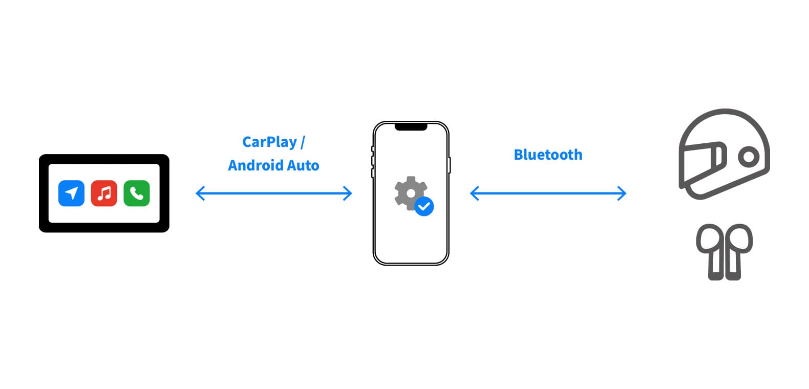
-
Confirm phone connection
Make sure CarPlay or Android Auto is active first.
-
Enable audio-device pairing mode
Put the Bluetooth helmet or headset into pairing mode.
-
Pair through the phone
Select the helmet or headset's Bluetooth name in the phone's device list.
Keep the devices within 3 m when pairing.
Connect only one audio device at a time.
Heavy rain may affect wireless signal stability.
08.02Connection checks
Check the phone's selected audio output and test at low volume while parked. Make sure the volume does not prevent you from hearing your surroundings. If there is no sound, see Chapter 13 for helmet/headset troubleshooting.
TPMS tire pressure monitoring — optional
This chapter applies only to kits with optional tire pressure sensors. Skip it if sensors are not installed.
Each kit includes two sensors, each with a CR1632 battery installed, plus the matching wrench and nuts. Use one sensor for the front wheel and one for the rear wheel.
09.01Preparation before pairing
-
Remove the valve cap
Remove the cap from the tire valve where the sensor will be installed.
-
Fit the locknut first
Thread the supplied anti-theft locknut onto the valve. Do not install the sensor yet.
09.02Tire pressure sensor pairing
The pairing method depends on the display version; both methods are not offered together. After tapping a wheel, use manual pairing if a code-entry window appears, or automatic pairing if “Pairing” appears. Follow the steps that match your actual screen.
09.03 Automatic pairing (automatic-pairing versions)
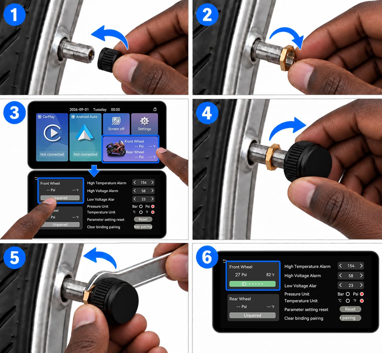
Sensor installation for automatic-pairing versions
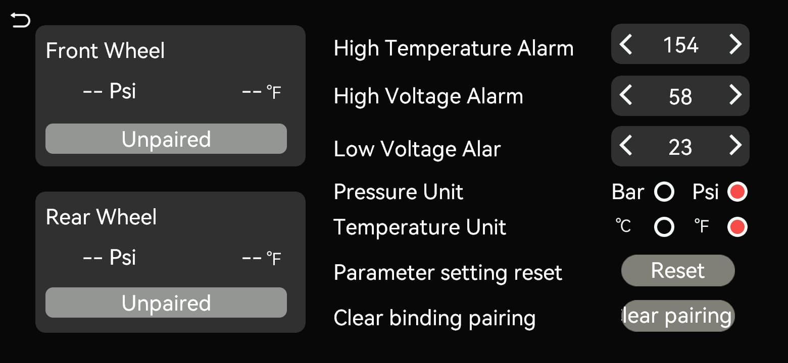
Tap the wheel to pair
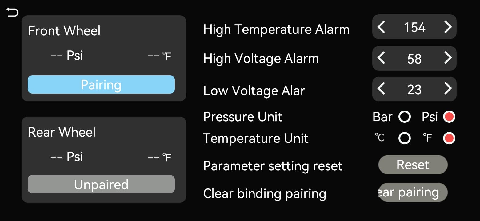
Pairing
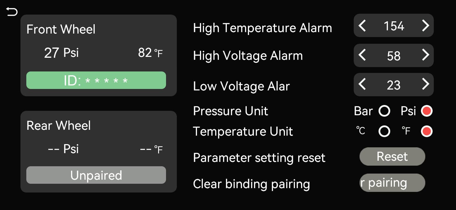
The wheel shows pressure, temperature and ID
-
Open the pairing screen
Enable Tire Pressure Informationrmation, then tap the motorcycle area on the home screen. Tap the front or rear wheel to pair and confirm that “Pairing” appears for that wheel.
-
Activate the sensor
After Pairing appears, screw the corresponding external TPMS sensor clockwise onto the tire valve until seated. The sensor transmits continuously after detecting tire pressure.
-
Confirm pairing
Automatic pairing succeeds when the display receives the sensor signal and updates the selected wheel's pressure reading.
-
Pair the other wheel
Select the other wheel and repeat these steps with the other sensor.
09.04 Manual pairing (manual-pairing versions)
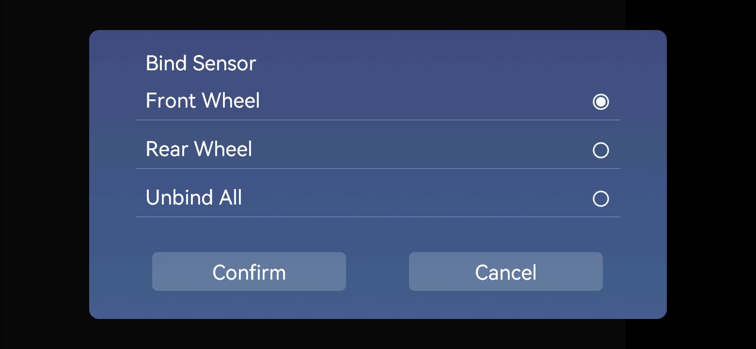
Bind Sensor: Front Wheel / Rear Wheel → Confirm
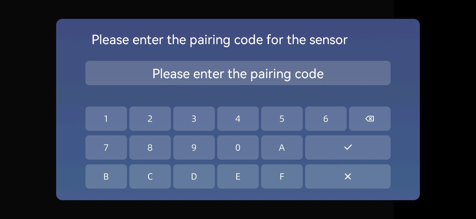
Please enter the pairing code for the sensor
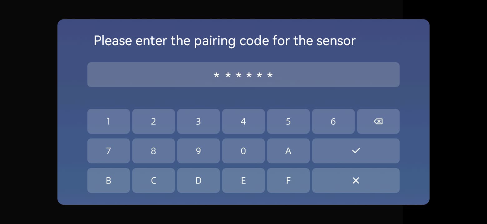
Enter the sensor's six-character code and tap ✓
Readings appear when pairing succeeds
-
Open the pairing window
Tap the motorcycle area on the home screen, then a wheel. In “Bind Sensor”, select “Front Wheel” or “Rear Wheel” as appropriate and tap “Confirm”.
-
Enter the sensor ID
Enter the six characters printed on the sensor and tap ✓ to confirm. Use the delete key to correct mistakes or tap × to cancel.
-
Activate the sensor
Screw the corresponding external TPMS sensor clockwise onto the tire valve until seated. The sensor transmits continuously after detecting tire pressure.
-
Confirm pairing
Manual pairing succeeds when the display receives the signal and updates the selected wheel's pressure reading.
-
Pair the other wheel
Select the other wheel, enter that sensor's six-character ID and repeat the pairing steps.
09.05Post-installation checks
Once the sensor is seated, hold it steady and use the supplied wrench to turn the preinstalled locknut back against its base. Do not loosen the sensor or bend the valve. Check the valve base and sensor joint for leaks. If a leak occurs, inspect the installation, seals and valve rather than applying more force.
Check that the on-screen wheel position matches the actual installation.
Check that the sensor and locknut are secure.
Check the valve area for leaks.
Before riding, confirm readings appear for every installed sensor.
09.06Replacing the sensor battery
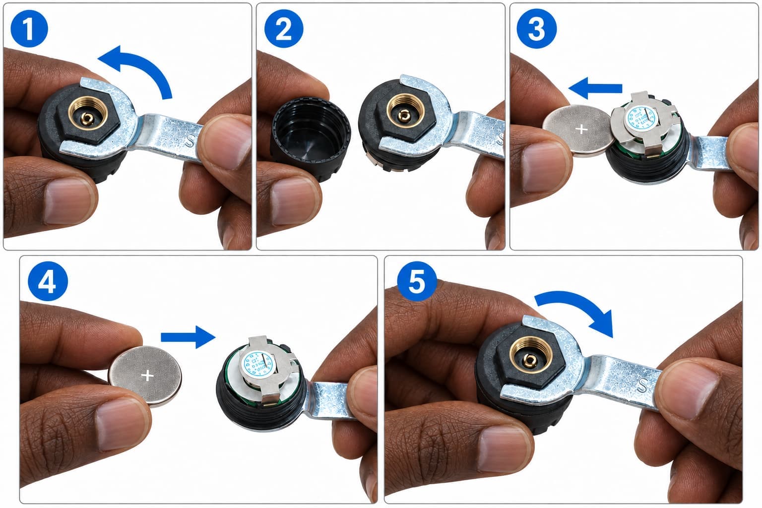
-
Remove the sensor
Park safely. Loosen the locknut with the supplied wrench, then unscrew the sensor counterclockwise.
-
Open the battery compartment
Hold the sensor housing steady. Fit the supplied wrench over the hexagonal protrusion on the bottom and turn counterclockwise to separate the housing from the internal assembly.
-
Remove the old battery
Note the battery polarity and slide the old CR1632 battery out from the side of the compartment. Do not pry on the circuit board or metal contacts.
-
Insert a new battery
Slide in a new CR1632 battery with the same polarity as the original. Make sure it is fully seated.
-
Check and close
Check that the sealing ring is clean, undamaged and properly seated. Reassemble the housing and internal parts, then tighten clockwise with the supplied wrench.
-
Reinstall and check
Reinstall the sensor on its original wheel, tighten the locknut and confirm pressure readings return. Repeat pairing if no readings appear.
09.07Alarm thresholds and abnormal pressure
Tire pressure settings and wheel information
Before setting thresholds, consult the vehicle or tire manufacturer's pressure requirements for the operating conditions. The sensor's measurement range is not a recommended tire pressure. If a reading or alarm is abnormal, park safely, inspect the tire, valve and sensor, and verify pressure with a suitable gauge. Do not ride until leaks or tire damage are resolved. TPMS does not replace routine tire checks.
System settings
The settings menu contains display, Bluetooth and system options.
10.01 General
Theme: Auto / Light / Dark.
English、简体中文、繁體中文、Français、Deutsch、Italiano、日本語、Português、Русский、Español、Polski、Türkçe、한국어、ภาษาไทย、Nederlands
Set Time: adjust the display's date and time.
Brightness: drag the slider to adjust brightness.
Tire Pressure Information: show or hide tire pressure information on the home screen.
10.02Bluetooth
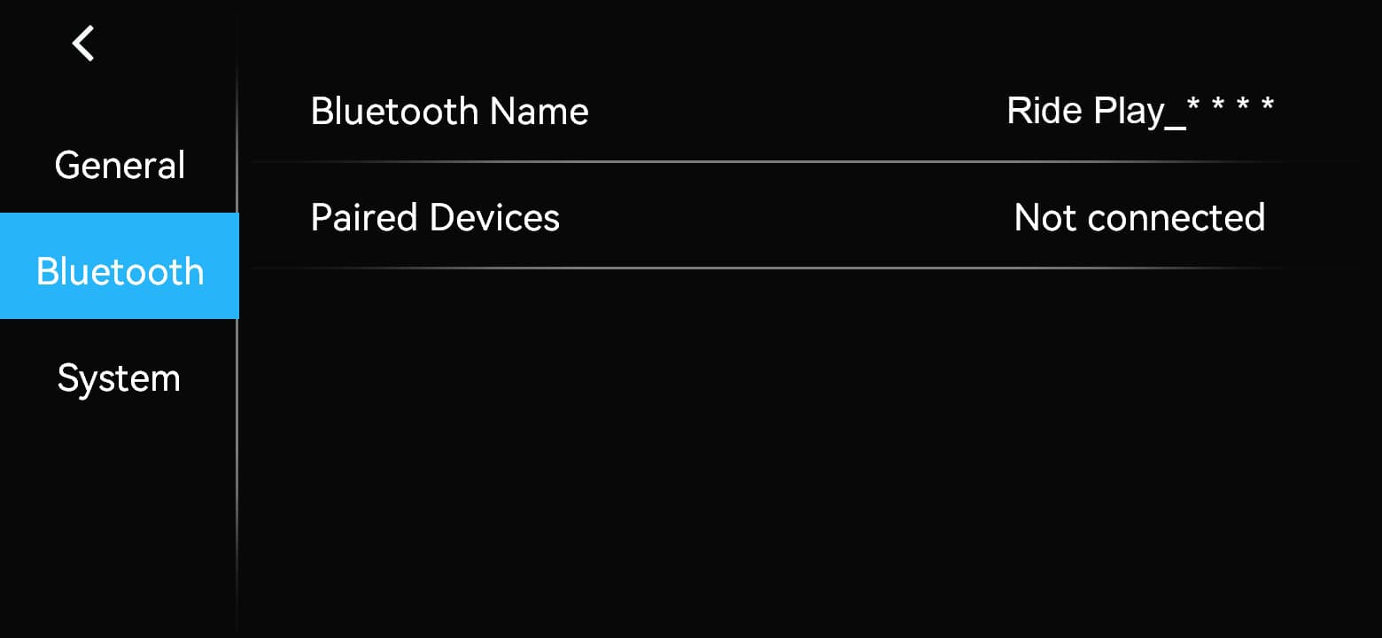
Bluetooth Name: check the device name, in the format Ride Play_****. The last four characters vary by device; select the actual name shown when pairing your phone.
Paired Devices: view connection status.
10.03System
About: Device Model / Serial Number / APP Version / MCU Version / Hardware Version. Scroll down to access “OTA Update”.
Startup Logo: choose a built-in image or a custom startup logo.
Restart System: restart the device.
Restore Factory Settings: clear user settings and restore defaults.
10.04Changing the startup logo
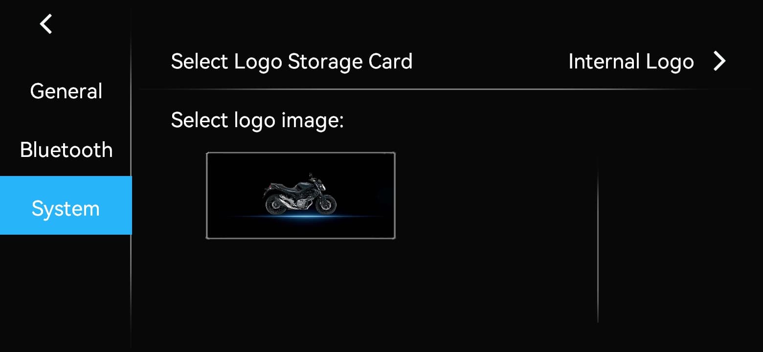
Internal Logo
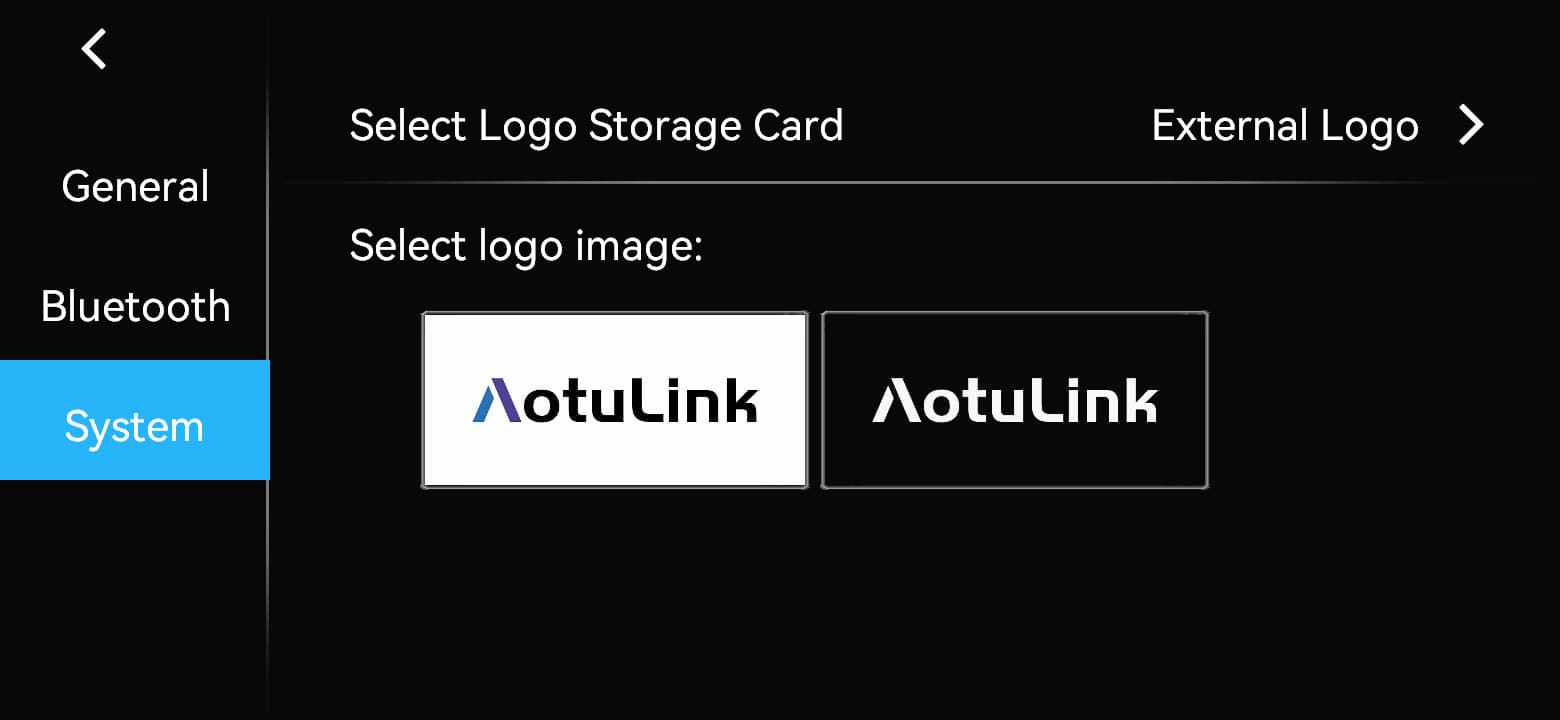
External Logo
Image requirements
File size: less than 300 KB.
File format: JPG.
Image dimensions: width less than 1024 px and height less than 480 px.
Use Windows Paint and select Save As > JPEG Picture to ensure the correct file format.
Procedure
-
Prepare the TF card
Create a folder named logo in the root directory of the TF card.
-
Copy the images
Copy JPG images meeting the requirements above into the card's logo folder.
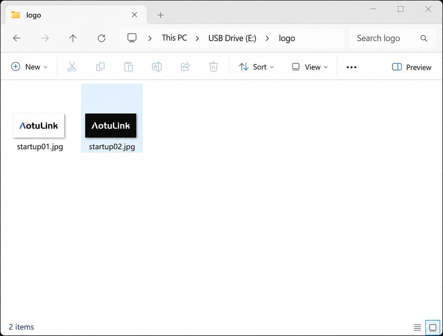
Place the JPG files in the logo folder
-
Switch off power
Turn the device off and disconnect power before inserting the TF card.
-
Remove the card-slot cover
The TF slot is on the bottom edge of the display. Use a suitable screwdriver to remove the cover screws, then remove the cover.
-
Insert the TF card
Insert the card in the correct orientation for the slot.
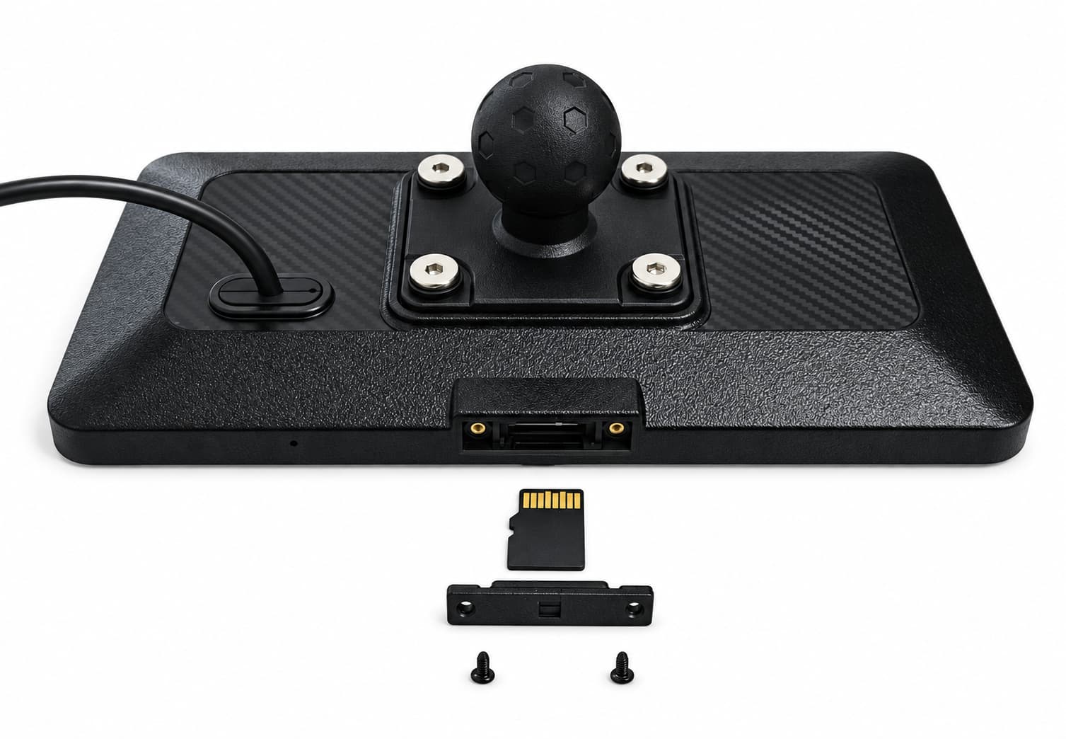
Card slot, TF card, cover and screws
-
Restore the waterproof seal
Check that the cover and seals are clean, undamaged and correctly seated. Refit the cover and tighten the screws.
-
Select External Logo
Switch the device on, open “Settings > System > Startup Logo > External Logo” and tap the desired image in the list.
-
Restart
Restart the device. The selected custom logo will appear during startup.
10.05 Restart versus factory reset
Restart reboots the device. Factory reset clears saved settings and pairing information. Record required settings, tire pressure thresholds and device information before resetting. Afterwards, recheck phone connections and optional TPMS operation.
OTA firmware update
Keep vehicle power and the phone hotspot stable throughout the update.
11.01Update steps
-
Open the update page
Open Settings > System > About, scroll down and tap OTA upgrade.
-
Set up the phone hotspot
Enable the phone hotspot and set its name and password as shown on the display. The current screen requires the name Car and password 12345678.
-
Confirm hotspot connection
Wait until the screen displays “Mobile hotspot connected successfully”.
-
Start the firmware update
Tap Firmware upgrade to download and install the update package. Downloads may take longer with a weak signal. Keep the hotspot and power supply stable.
-
Wait for automatic restart
Do not disconnect power or operate the device during the update. The display restarts automatically after a successful update. Check the version and common functions afterwards.
11.02Checks after updating
Confirm that the device restarts normally.
Open Settings > System > About and check the software version.
Check phone connectivity, Bluetooth, tire pressure monitoring and other common functions.
11.03Additional update advice
Update only while safely parked, with stable power and phone network coverage. Record the current software version first. The hotspot may use mobile data. After the update, restart and functional checks are complete, you can turn off the temporary hotspot or restore its original settings.
Routine maintenance
For display removal, cable repairs or seal replacement, contact a competent installer or customer support. Replace sensor batteries as described in Chapter 09.
12.01Before every ride
Check that the display and mount are secure and do not obstruct your view. Check cables for wear or pinching, free steering movement, and closed card-slot and visible seals. With TPMS installed, check valves for deformation or cracks, secure sensors and locknuts, adequate clearance and no leaks. Verify cold tire pressure. Correct wheel assignments and normal readings do not replace physical checks. See Chapter 09 for valve safety requirements.
12.02Cleaning the screen and housing
Park safely and switch the device off. Wipe the screen and housing gently with a soft, clean cloth, slightly dampened if necessary. Keep liquid out of ports. Do not spray cleaner directly on the device or use abrasives, strong solvents or hard scraping tools. Contact support if dirt cannot be safely removed. Let the surface and areas around ports dry completely before use.
12.03Checks after rain or washing
Wipe away surface water and inspect the housing, ports and TF slot cover. Dry the surrounding area before opening the cover. Do not use pressure washers or steam cleaners. Stop using the device and contact support if seals are damaged or internal condensation or water ingress is suspected. Do not disassemble or heat the device. For IP67 conditions and limits, see Chapter 01 。
12.04Mount and cable checks
After long trips or heavy vibration, park and check the mount and cables again. Inspect and resolve any looseness, wear or damage before use. Confirm everything is secure. Do not compensate for damaged parts by overtightening them.
12.05TPMS maintenance
Clean the sensor exterior and inspect the valve and locknut. After replacing a battery or reinstalling a sensor, follow Chapter 09 to check seals, wheel assignment, readings and leaks. Battery life varies with operating conditions.
12.06Storage and returning to use
Switch off and keep the device dry before storage. Avoid prolonged direct sunlight. Storage temperature: -30 °C to 80 °C. Follow the vehicle manual for battery care during prolonged parking. Before reuse, inspect the housing, cables, seals and mount, then check date/time, phone connections and installed TPMS. Operating temperature: -20 °C to 70 °C.
12.07Recycling and disposal
Sort packaging for appropriate local recycling. Ask your local electrical-equipment recycling service how to dispose of the product. Do not burn it. Follow Chapter 09 to safely remove replaceable sensor batteries. Keep new and used batteries away from metal objects to prevent short circuits, and use appropriate local battery recycling services. Do not disassemble the display for recycling yourself.
Troubleshooting
These checks do not require disassembly or modification. If the problem remains, stop using the device and contact support.
13.01Power, screen and time
Device does not start
Check B+, ACC and GND wiring, ACC voltage with ignition off and on, and loose connections.
Next: stop using the device and contact the installer or support.
Device does not shut down with ignition
Check that the red ACC wire connects to the correct switched ACC supply, not a permanent supply.
Next: verify the vehicle wiring again.
Blank screen with power connected
Tap the screen to wake it. Check whether Screen off was selected and check brightness settings.
Next: restart the device.
Touchscreen unresponsive or slow
Dry the screen and your fingers, remove gloves that may affect touch input, and wait for the current operation to finish.
Next: restart the device. Contact support if it still does not respond.
Device restarts repeatedly
Check secure B+, ACC and GND connections, stable supply voltage and loose cables.
Next: stop using the device and contact the installer or support.
Incorrect date or time
Check time settings and phone connectivity.
Next: reset the date, time and display format.
13.02Phone connection and Bluetooth audio
CarPlay does not connect
Check iPhone Bluetooth and Wi-Fi, confirm the device name and delete old pairing records.
Next: repeat the first-connection procedure.
Android Auto does not connect
Confirm Android 11.0 or later, enable Bluetooth and Wi-Fi, and delete old pairing records.
Next: repeat the first-connection procedure.
CarPlay or Android Auto disconnects frequently
Move the phone closer, check Bluetooth and Wi-Fi, and turn off battery-saving mode, hotspot or VPN.
Next: restart both devices. If necessary, delete pairing records and pair again.
No sound from helmet or headset
Check that the audio device is paired to the phone, only one audio device is connected, and the distance is within 3 m.
Next: check the phone's audio output selection.
13.03TPMS problems
No tire pressure readings
Check that TPMS is enabled, the correct front/rear wheel is selected, and the sensor is properly installed.
Next: pair the corresponding wheel again.
Readings assigned to the wrong wheel
Check whether front and rear sensors were swapped and whether the correct wheel was selected during pairing.
Next: remove the affected pairing and pair again.
Air leak after sensor installation
Check correct sensor and nut installation, and inspect the valve and seals for dirt or damage.
Next: remove the sensor and refit the valve cap immediately. Do not ride until the leak is resolved.
13.04OTA update problems
OTA update does not start
Check the hotspot name Car and password 12345678, mobile data availability and hotspot connection limits.
Next: restart the hotspot and try the update procedure again.
OTA download stalls or stops
Keep power connected and check the phone network. Prevent battery-saving or screen-lock settings from switching the hotspot off.
Next: retry the update after the network recovers.
OTA update fails but the device still starts
Record the software version and error message. Check stable power and network connectivity.
Next: retry once only. Contact support if it fails again.
Device does not start after an OTA update
Do not repeatedly disconnect power, flash firmware, disassemble the device or attempt unguided recovery procedures.
Next: stop using the device and contact support.
13.05When to stop using the product
The device, cables or connectors show damage, burning, unusual odors, smoke or excessive heat.
The display or mount is loose and may fall off or interfere with vehicle control.
Product operation causes faults in the vehicle electrical system.
The device malfunctions after water ingress or a severe impact.
Technical support
Prepare device information and a description of the fault before contacting support.
14.01Self-service support
Official website: https://www.aotu-link.com
For personal after-sales assistance, expand and complete the “14.02 After-sales support request” form below. Providing the information at once helps us respond more efficiently.
If the form is unavailable, email support@aotu-link.com with the product model, purchase channel and a description of the issue.
Live support: click the blue chat icon on this page. You can chat directly when an agent is online.